2013-12-29

Fried 2 other FMD2740A stepper drivers

This is the second time I fried 2 FMD2749A stepper drivers on my TravelCNC.
Made 2 giant Hackcenter calls at the 30C3 hacker congress stink of fried electronics while the people from CCCfr ripped out all power cables they could find, called me and got a fire extinguisher.

The drivers are advertised to be operated at up to 50V.
The first one had a 5V DC converter (LM2576S-5.0) inside that is only rated up  45V instead of an " LM2576HVS-5.0" rated up to 60V.
I'm using them with a common 48V power supply. Well within the rating of the dealer.
Now, after 3 fried stepper drivers the dealer "Thomas Wu" answered that the drivers where actually only good for 45V!!!
I wouldn't ever but any power electronics from this Thomas Wu guy on Aliexpress again!

I turned down the power supply to 44.5V (can't go lower then that on the potentiometer)
and am waiting for some new 5A drivers with over-current, over-heating, under-current,... protection.
One of these drivers is working fine at 48V driving the super-strong 4th axis, so I hope they will hold up.


2013-12-11

Reverse Engineering (Micro) Four Thirds lens protocol

Based on the work of Lasse Bayer, who modified an Olympus lens to attach a logic analyser,
I'm trying to reverse engineer the rest of the Micro 4/3 lens protocol.

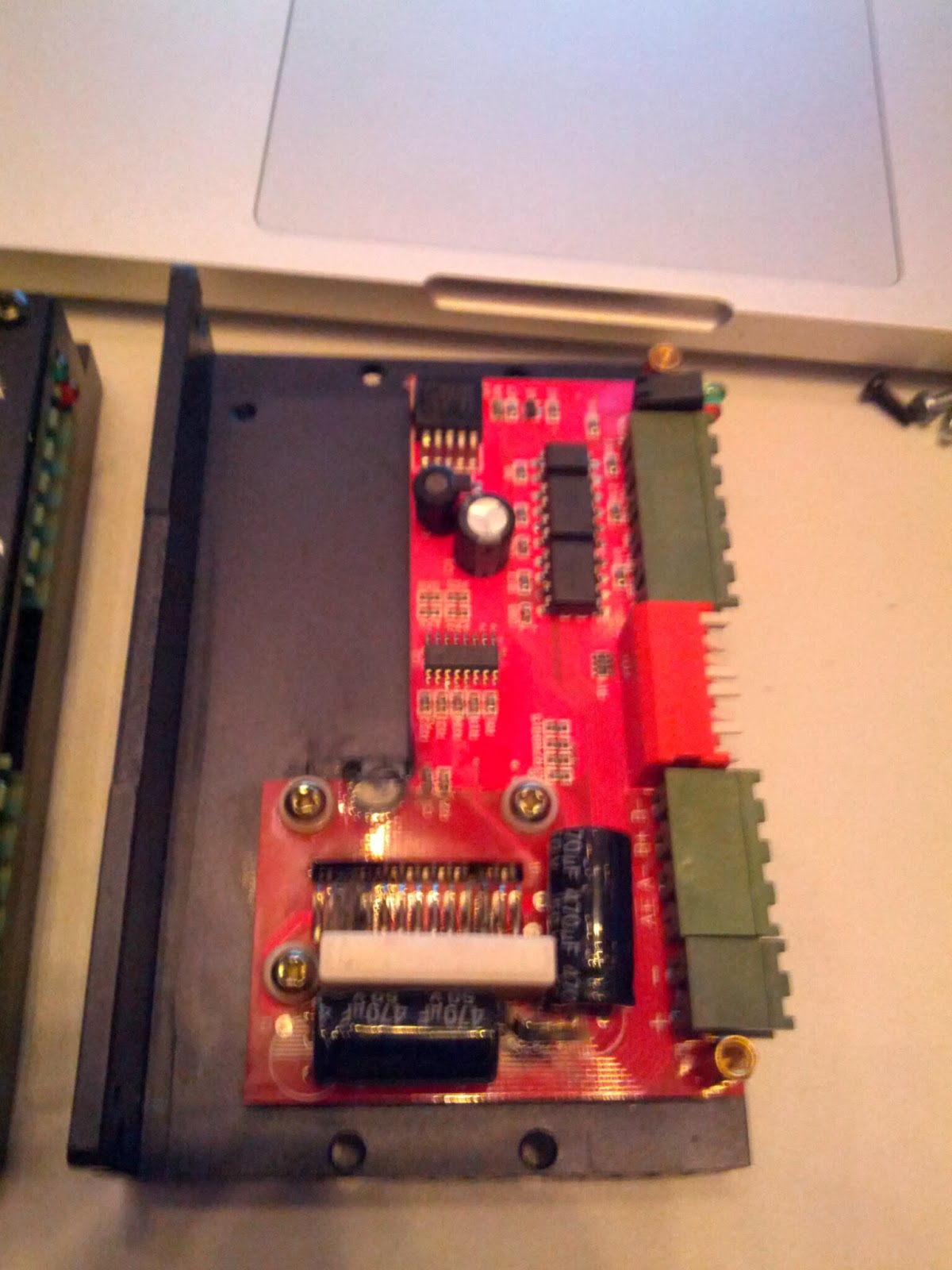
I found an interesting macro adapter that sits between mft camera and mft lens and has electrical contacts.
Thus I'm trying to modify this adapter and analyze not only one lens but a large number of combinations of lenses and cameras.

I'm currently working on this.
This blog-posting will be updated all the time!
Here are the logs!

Setup 


Pinout:

VDD=microcontroller power (goes low on lens-release button)
VCC=battery power (possibly for AF-motor,...)

preliminary MFT pinout:


signallogic analyser cablelogic analyser channelposition


ACK?BROWNCH4Right when Facing the Sensor
ACK?REDCH2
ClockORANGECH3
DataYELLOWCH1
Lens2Body?GREENCH0
Body2LensBLUECH5

GREYCH7
???PINKCH6

WHITEGND

BLACKGND
FEHLER(N/C)------Left when facing the sensor


Quote about the 2 additional contacts (from here):
In addition, the lens mount of the Micro Four Thirds System is equipped with two additional signal contacts for smoother Live View shooting with shorter time lags, faster higher communication speeds between the lens and body, and, of course, reduced lens and camera size.
These two contacts will also be used in high-speed data processing required for the movie handling capability expected in the future.


(Image again taken from Lasse Bayer)


SPI seems to be used at 500KHz with 8 bits LSB. Lens2Body and Body2Lens are pulled high by lens or body respectively to indicate that they are ready to receive/send the next byte and pulled low again to acknowledge the receipt.

The camera seems to pull the lines low (including clock) to pause communication.
  • when the shutter is pressed
  • when exposure has finished 
(confirmed for MFT)

General protocol

Everything seems to start with 4 byte commands sent by the camera to the lens,
followed by the lens answering.

Initial communication 

FT:  B0 F0 00 00  (first command on switch-on)
MFT: B0 F0 00 00 
 
FT: 
Followed by 2 values: A0 00 
 
MFT:
Followed by 2 values: 00 00 


Command: request lens data (MFT)

MFT: 80 ED 01 00
 
TODO: followed by some yet unknown data

Command: request lens data (FT)

FT:  C0 F0 20 00
There is quite a lengthy answer in 26 blocks: 

 Block 0

lens Id
lens designation(ASCII)
lens serial number
lens firmware version
number and length of the following blocks

 TODO : details

Block 1

 May be a list of all focal lengthes in mm - 1

Block 2

unknown

Block 3

unknown

Block 4

unknown

Block 5

unknown

Block 6

unknown

Block 7

unknown

Block 8

unknown

Block 9

unknown

Block 10

unknown

Block 11

unknown

Block 12

unknown

Block 13

unknown

Block 14

unknown

Block 15

unknown

Block 16

unknown

Block 17

unknown

Block 18

unknown

Block19

unknown

Block20

unknown

Block21

unknown

Block22

unknown

Block23

unknown

Block24

unknown

Block24

unknown

Block25

unknown

Block26

unknown

Regular polling (MFT)

 TODO: MFT seems to use multiple, regular polls.

81 E3 04 03
followed by yet unknwn data that does change while not touching the camera.

Regular polling (FT)


C0 F1 0 0 
Apparently the camera polls the lens every 104ms sending these 4 bytes.
The lens answers with 14 bytes including information on the current focus, focus mode, zoom distance, and a checksum.

(I'll insert details here)

Here is what Lasse found out:
 Byte Number:

 1 ,  2 ,  3 ,  4 ,  5 ,  6 ,  7 ,  8 ,  9 ,  10,  11,  12,  13,  14,  15,  16,  17,  18
----------------------------------------------------------------------------------------

    Infinity focus:

192, 241,   0,   0, 177,  11,   0, 160,   0,  31, 255, 255,   2,   5,   0,   0,   0, 196

    Focusing closer:

192, 241,   0,   0, 177,  11,   0, 128,   0,  31,  43,   1,   2,   5,  11,   2,   0, 223
192, 241,   0,   0, 177,  11,   0, 128,   0,  31, 155,   0,   2,   5,  85,   3,   0, 153
192, 241,   0,   0, 177,  11,   0, 128,   0,  31,  87,   0,   2,   5, 121,   5,   0, 123

    Close focus:

192, 241,   0,   0, 177,  11,   0, 144,   0,  31,  78,   0,   2,   5, 254,   5,   0,   7

----------------------------------------------------------------------------------------

Byte 8:   0 - 0000 0000 - Single Autofocus active
        160 - 1010 0000 - Manual Focus @ infinity
        144 - 1001 0000 - Manual Focus @ close-up
        128 - 1000 0000 - Manual Focus in between

Byte 10: Changes linearly while zooming from 31 @ 45mm to 0 @ 14mm

Bytes 11 + 12: FF FF - 65535 - infinity focus
               4E 00 -    78 - close focus
               Focus distance ?

Bytes 13 + 14: Seem to depend on the zoom position at switch-on.
               Do not change while zooming or focusing manually.

Bytes 15 + 16: 00 00 -     0 - infinity focus
               FE 05 -  1534 - close focus
               Focus mechanism position ?

Byte 18: Checksum of Bytes 8 to 17, maybe 7 to 17

The first 4 Bytes are sent from Body to Lens, the remaining 14 from Lens to Body.

Command: Start/Stop exporure (FT)

A0 B0 FE  0  ? stop of exposure ?
A0 B1  0  0  ? start of exposure ?
 TODO: different on MFT

Command: Change Aperture (FT)

Like the polling is a 4 byte sequence, this seems to be 4 byte too.
close aperture: 176  210 xxx xxx
open aperture:  176  215 0   0
 TODO: verify list of epertures

Aperture values as determined by Lasse:
aperture         command
value               data
                   
estimated
                   
1.0               0    0
1.1              85    0
1.2             170    0
1.4               0    1
1.6              85    1
1.8             170    1
2                 0    2
2.2              85    2
2.5             170    2
2.8               0    3
3.2              85    3
3.5             170    3
                   
determined                my own notes:
4                 0    4  (base value for comparison) 
4.5              85    4   (+85 )
5.0             170    4   (+170)
5.6               0    5   (+256)
6.3              85    5
7.1             170    5
8                 0    6
9                85    6
10              170    6
11                0    7
13               85    7
14              170    7
16                0    8
18               85    8
20              170    8
22                0    9

 determined
                   
3.5             157  131     my own notes:
3.6             171  131
3.7             198  131
3.8             211  131
3.9             236  131
4.0             248  131     (base value for comparison) 
4.1              17  132
4.2              28  132
4.3              51  132
4.4              62  132
4.5              84  132     (+77 instead of +85 =-10%)
4.6             106  132
4.7             116  132
4.8             137  132
4.9             156  132
5.0             166  132     (+162 instead of +170 =-5%)
5.1             176  132
5.2             195  132
5.3             213  132
5.4             222  132
5.5             231  132
5.6             249  132     (+257 instead of +256 =+0,4%)
 
 
Quote from a camera manufacuter I recently got:
"The electronic feedback from the lens tells the camera where it is in 
regards to f-stop, and the camera then interprets that information." 

Command:  shutdown (MFT)

Sadly the shutdown sequence seems to use different commands.
No clear command sequence to see yet.

-->
14-42PZ14-42PZ14-42PZ
14mm14mm14mm14mm


23,89ms12,32ms32,09ms
14,06ms29,83ms21,92ms23,86ms
SDO: A1 D7 00 00 11 05 7D 07 SDO: F1 CF 00 00 11 05 7D 07 SDO: B1 D7 00 00 11 05 7D 07
SDO: 31 CF 00 00 08 04 3F 02 SDO: 31 C7 00 00 08 02 BF 00 SDO: 21 9E 00 00 00 00 3F 00 SDO: F0 9E 00 00 80 00 BE 06
SDI: A1 D7 00 00 11 05 7D 07 SDI: F1 CF 00 00 11 05 7D 07 SDI: B1 D7 00 00 11 05 7D 07
SDI: 31 CF 00 00 08 04 3F 02 SDI: 31 C7 00 00 08 02 BF 00 SDI: 21 9E 00 00 00 00 3F 00 SDI: F0 9E 00 00 80 00 BE 06


lens folding up...lens folding up...lens folding up...


716,8ms705,43ms725,16ms
336,96ms352,76ms344,85ms346,89ms
SDO: 42 FF 07 00 C6 16 02 00 SDO: 62 FD 03 00 C6 16 02 00 SDO: 42 FF 03 00 C6 16 02 00
SDO: E2 FF 07 00 60 08 00 00 SDO: 62 FF 03 00 C2 12 00 00 SDO: 42 FE 07 00 C0 10 00 00 SDO: E0 FF 07 00 C0 10 00 00
SDI: 42 FF 07 00 C6 16 02 00 SDI: 62 FD 03 00 C6 16 02 00 SDI: 42 FF 03 00 C6 16 02 00
SDI: E2 FF 07 00 60 08 00 00 SDI: 62 FF 03 00 C2 12 00 00 SDI: 42 FE 07 00 C0 10 00 00 SDI: E0 FF 07 00 C0 10 00 00


790,6ms761,32ms794,78ms
393,21ms414,12ms370,9ms384,84ms
SDO: 7C 31 10 SDO: 7C 31 10 SDO: 7C 31 10
SDO: E0 00 08 SDO: C0 00 0C SDO: E0 00 18 SDO: E0 00 18
SDI: 7C 31 10 SDI: 7C 31 10 SDI: 7C 31 10
SDI: E0 00 08 SDI: C0 00 0C SDI: E0 00 18 SDI: E0 00 18


VDD going lowVDD going lowVDD going low
VDD going lowVDD going lowVDD going lowVDD going low


I also looked at this on the Blackmagic Pocket Cinema Camera...
not only does the #BMPCC not send the proper lens shutdown sequence, it also has some really bad noise on the VDD line while being switched off. 

Command: prepare for shutdown (FT)

176 160   0   0         prepare for shutdown
 TODO: verify 

Command: focus

176 161 xxx xxx  change focus to/by value
176 173   0   0  start single autofocus
 TODO: verify 

 Other commands

192 241   0   0  poll
192 246   0   0  ?(sent after initial command and before requesting the full lens data))

192 250 xxx xxx  ?
192 251   0   0  ?
  TODO: analyse these

2013-11-04

BMPCC LANC and Sysclk DX (USBee DX clone)


I received my Sysclk DX from China. It's an affordable clone of the USBee DX.
A 2 channel USB Mixed Signal oscilloscope paired with an integrated 16 channel logic analyser.
The first task I'm giving it is to analyse the LANC protocol on the Blackmagic Pocket Cinema Camera.
Why? Because I need to have a way to meassure what's supposed to be on the wire and what is actually there to implement LANC into an Atmel microcontroller and build a better LANC remote. ;)

First try:
On a breadboard I pulled the data line high and tried to analyse the signal. The camera is supposed to send data packets... absolutely no luck. :(

Second try:
I put the breadboard in between a working LANC remote and the camera and ran the logic analyser.
I may be doing something wrong but I can't see anything on the wire. The LANC remote however works fine!

UPDATE: Third try:
I dumped the Sysclk DX and got my old Usbee AX and it worked fine.
I found the following LANC commans on the Blackmagic Pocket:
//LANC(0x18, 0x33); //send REC command to camera
//LANC(0x28, 0x45); //send MANUAL FOCUS FAR command to camera
//LANC(0x28, 0x47); //send MANUAL FOCUS NEAR command to camera
//LANC(0x28, 0x53); //send IRIS+ command to camera
//LANC(0x28, 0x55); //send IRIS- command to camera

LANC(0x28, 0x43); // AUTO FOCUS  
Update: Blackmagic answered: IrisAutoAdjust =  0x28 0xAF
I search in the area of 0x55 and 0x47 but could not find anything that triggers auto iris or auto focus.
Aparently these commands do exist but I don't know the command code.

UPDATE:
Using the code from "Control your camera" it seems to work more reliable when removing the -8ms adjsutment for the digitalWrite command and replacing that with a macro from here:

#define fastWrite(_pin_, _state_) ( _pin_ < 8 ? (_state_ ?  PORTD |= 1 << _pin_ : PORTD &= ~(1 << _pin_ )) : (_state_ ?  PORTB |= 1 << (_pin_ -8) : PORTB &= ~(1 << (_pin_ -8)  )))
// the macro sets or clears the appropriate bit in port D if the pin is less than 8 or port B if between 8 and 13


my send-byte routing now looks like this:
void send_8(char dat) {
  char abit;
  char index;
  for(index = 0; index <= 7; index++) {
  abit = ((dat>>index) & 0x01);
  if(abit==1) {
    fastWrite(cmdPin, HIGH);
  } else {
    fastWrite(cmdPin, LOW);
  }
  delayMicroseconds(bitDuration);
}

//Byte is written now put LANC line back to +5V
fastWrite(cmdPin, LOW);

}


Also: I can successfully power the Arduino Uno from the LANC cable.

2013-10-24

Soundproofing the TravelCNC


The TravelCNC already has an inner lining of Basotect acoustic foam on the inside.
(Not all of it mounted yet because I'll improve some of the cabling hidden below the foam.)
This helps a great deal with high frequencies.
For the low frequencies I have a heavy, 10mm thick rubber sheet below the actual machine.

It turns out that this is not enough. I get a great deal of vibration that can actually be felt on the wooden stage box.
Next idea: there are 4 bolts going through the rubber and mounting the machine to the case.
I'mm try to widen the holes in the wood and install sound insulating bolt anchor fittings to insulate the bolt from the hole in the wood.

...let's see of that helps.


2013-11-13 UPDATE
I finally finishd the sound proofing


2013-10-22

Fixing the 4th axis on the TravelCNC and breaking my tools


Since I mounted a larger stepper motor to the 4th axis on my TravelCNC (portable hobby sized CNC in a custom flight case), I needed to raise the 4th axis by 10mm.
Else the longer stepper would collide with the frame.


This means that the tailstock is now too low.

So yesterday and today I milled myself a spacer out of some wood to keep the tailstock at the correct height.


It worked...but when I tried to use it, I made a terrible mistake.
I wanted to use the edge finder to find the right and left edge of the cylinder I mounted.
I knew it was perfectly round, so the center of rotion would match the center of the cylinder.
....so I mounted my mechanical edge finder...switch on the spindle to rotate it slowly

...and forgot that the spindle was still set to 10'000RPM.
It ripped my trusted edge finder apart.

Now you can get mechanical edge finders for 3-4eur in China, no problem.
You can even get cool electronic ones for 10eur.
However all the mechanical ones are 10mm shank and the electronic ones 20mm shank.
The maximum my ER11 collets can mount is 7mm.

I would really like to modify one of these electronic ones. Attach it to the electronic probe input and find edges extremely accurately without jogging back and forth.
However the back is also the battery cover. So I can't simply mill it down from d=20mm to d=7mm. :/

2013-10-19

MY BMPCC review

I just received my Blackmagic Pocket Cinema Camera last night.
In this blog posting I'm trying to collect my findings about it to help others decide on it's maturity.

untested


  • LANC focus control
  • LANC IRIS control (command codes unknown)

confirmed features

  • LANC start+stop
  • very fine and organic grain

confirmed, known issues

  • very low audio levels with internal or external microphone (Sennheiser MKE400 with levels "+")
  • constant white noise in audio
  • Focus button is extremely slow (2-4 second for a Leica lens that focuses in less then 1/10s)
  • no OIS on 14-42PZ
  • extremely short battery life
  • seldom dropped frames (3-4 frames on a total of 45min of 1-5 minute recordings) using Patrion Memory EP-Series 64GB UHS-1 SD-card

new issues

  • 14-42PZ does not shut down properly on BMPCC (lens doesn't collapse)
  • LANC cannot control the zoom on the 14-42PZ, ,14-42 II, 42-175 PZ and 100-300 using the Manftotto 484LNC (my fault. DAQ states that ZOOM via LANC is unsupported. :( )

feature requests

  • manual aperture control in the menu
    • you can do that. You have to press IRIS and the up+down buttons right below. Imposible with one hand. Difficult with 2 hands.
  • display of remaining minutes on SD-card
  • audio levels
  • deletion of clips in camera
  • formating SD-cards in camera

Links 

2013-10-17

Tailstock height adapter for my TravelCNC

The original 4th axis on my TravelCNC was mounted so low, you can't even extend the arms of the chucks beyond the diameter of the chuck itself without hitting the table.
It was also so weak, that you could rotate it with 2 fingers while it tried to rotate the other way with all it's force.

So now I have a NEMA23 longneck stepper with tons of holding torque...and I can't mount it because it collides with the table.
Luckily it already came with a 10mm high alumimum plate to be mounted on the T-Slots.
What I did was to mill a small spacer out of wood to get the tailstock to the same Z+10mm height because obviously both have to match.

As it turned out, I had the wrong tool diameter in my CAM and it was 2mm too short.
..but that's easily fixed with hand tools while cutting it out.
(I don't want to cut it out with the CNC because I have no scrap-wood below it to ensure a flat surface.)


2013-09-27

The perfect multitool

I think I found the perfect multitool for me.

What I found I need are:
  • LED lamp
  • pliers
  • phillips #1 screwdriver
  • flat screwdriver
  • knife
  • sometimes a bottle opener (although Germans open bottles with just about everything...except bottle openers.)
  • wire strippers would be handy but not needed.
I like full sized multitools but they tend to stick out in an office environment, so I can't wear them all day (wich is kind of a point of having such a tool on your belt).
Instead I carry 3 tools:

The first thing I carry on my belt is a foldable and very tiny xacto-knife. Extremely tiny, extremely sharp and with a number of replacement blades inside. I think I'll keep that.
It's similar to this one except in color and name and that it comes with a tiny belt holster:


I had to ditch a small chinese tool at the airport, having forgotten to put it into the checked in luggage
(Not because of the knife...but because it had a screwdriver. Aparently airlines are afraid Germany Engineers can do just about anything given a screwdriver and duct tape.).
In San Francisco I got myself a Portland Coast  C2899.


I also carry a small 1xAAA flashlight but can't find a belt holster tiny enough for it.
The Coast was supposed to replace it because it already HAD a flashlight.
...only that it was way too weak, required a size of batteries you don't easily get in continental Europe and constantly empty because the button was accidentally pushed by just about anything in your pocket.
...and it didn't come with a belt holster.

Now I found something else.
A chinese dealer named Yuki Guan sells a RUISS RS1016A.
It doesn't show but he answered that it's also avaliable in black and it comes with a very sturdy belt holster.
It has the same, nice grip that the Portland Coast one has but the LED lamp is bigger and cannot be activated accidentally anymore.

custom XL45 pulley for 8mm D-shaped shaft


My CNC milling machine has a weak 4th axis.
I want to attach a larger stepper motor with seriously mor torque.
However that motor has a D-shaped 8mm shaft while an XL45T10 pulley always has a 6mm shaft.
I ordered a conventional one, hoping to drill it up but it was stuck in transit (damn Hermes. An envelope would have worked better.).
So I had to design a custom pulley that could me machined without a rotary axis (less of a top guard) and fits snugly onto an 8mm shaft.

In fact, I'm 3d printing a first one and plan to do the final one with a full sized top guard on the, thus fixed, 4th axis.


    2013-09-25

    Blown stepper driver

    After doing some test cuts yesterday I'm doing the first real milling on my TravelCNC today.
    I want to find out if it doesn't loose any steps now.

    First problem:
    after switching it on there was smoke any my Y-stepper driver went belly up.
    The FMD2740A stepper driver is rated  for 12-50V DC input.
    Internally they use an LM2576S-5.0 to generate 5V.
    Maximum input voltage 45V.
    ...They do not use the LM2576*HV*S-5.0 with a maximum input voltage of 60V.
    And I'm using a 48V power supply.
    ....go figure.


    Update: The chinese dealer very forthcoming and is even offering to pay for the repair (shipping to china and back to get a replacement with the same chip is expensive, time consuming and not a permanent solution).

    I now connected the Y stepper to the A channel, set MACH3 to interpret the A channel as  a linear axis and search&replaced the axis in the g-code.
    It's not cutting.....
    The operation will take 2x 1h . That should be enough to detect any lost steps. Particularly in Z.
    Touching the hand weels on the steppers there is no jittering. So it looks good.


    Update: Test was a SUCCESS. No lost steps whatsoever anymore!!! Very smooth operation for multiple hours and interrupted with shutting down the machine for a night before resuming.

    Update: My replacement FMD2740A died too. (during 30C3) Post mortem showed a bad solder joing on capacitor 1.

    Update:  2 other stepper drivers blown. Dealer "Thomas Wu" confesses they are only good up to 45V. Not 50V

    2013-09-24

    TravelCNC doing it's first cuts

    My TravelCNC reached it's most important milestone!

    The mobile CNC workshop in a custom made flightcase now has completely new electronics and made it's first cuts using it.
    It's now a usable, mobile 4 axis CNC milling machine.
    ...soon it will also be 3D printing and vector cutting.

    TODO:
    • add Basotect sound proofing
    • connect the USB control board to the spindle controller (speed in software)
    • add table legs to the top panel to use it as a collapsable work table
    • test 3D printing (ThingOMatic already disassembled, should work)
    • Replace 10A power socket with 16A version
    • add IP64 power sockets (you always need power socket in a workshop)
    • add mounting for vector knife (like drag-knife but cutting real 90° angles)


    2013-09-11

    The last honours for my Thing-o-Matic

    Looking at this blog, it must feel like I'm not doing nothing at the moment.
    This is far from the truth. Since I tried to keep things focused and have just one blog-post per project with all the infos one would need to replicate my work.

    Problem is: Where does one project and the next begin.

    Yesterday I prepared the new electronics for my TravelCNC.
    Today I gave my untrusty ThingOMatic the last honours and dismantled it.
    I'll keep the main boards, the extruder controller and the extruder stepper driver.
    However the mechanics will be that of my TravelCNC.
    Mach3 will control the CNC's motion and also give STEP+DIR pulses to the extruder stepper driver.
    The external display and keypad will help me set just the temperature while Mach3 executes the g-code. (With the extruder=E axis renamed to A.)

    One thing I noticed was that the GND cable of the extruder heater had molten it's mounting port.
    Since the extruder never had any issues with heating up or keeping hot, this doesn't seem to have had any impace. The cable never moved after all.


    Excuse the pool photos as  I didn't bring any of my cameras to this location.


    2013-07-04

    Travel CNC/3d printer/vector cutter combination


    There are people who have a travel toothbrush.
    There are people who have a travel hair dryer.
    For years I had a travel 3d printer.
    So why can't I have a travel CNC? ;)
    So why can't we have CNC mill, 4th axis, 3d printer, vector knife and resin casting and a work table in a single, mobile, quiet, clean tool?

    Here's the plan:
    1. disassembly my old, unreliable Thing-o-Matic to reuse the (non-original) toolhead and extruder controller.
    2. mount it onto a not-too-small (400x300), very quitet, 4 axis CNC milling machine
    3. make sure I can swap between CNC spindle, 3d printer and mounting the 4th axis to orient a vector knife
    4. put everything into a custom made stage box including locks, cooling-grills and properly sunk cable holes and a low enough side wall to reach the part you're working on easily
    5. sound proof the box
    6. Fit drawers for small parts, legs to make the box-lit a table, light and enough power sockets.
    7. win!
    Sounds easy enough, doesn't it?
    I have the CNC right here (awaiting a conversion to USB while converting my large CNC machine from USB to Ethernet and from 4 to 5/6 axis), ordered foam and box and am 3D printing the adapter to use the 3D printing head and all other alternative Makerbox heads I have.

    THIS BLOG POSTING GETS UPDATED REGULARLY AS THE PROJECT CONTINUES.

    Updates:
    2014-04-13
     Prepared a metal XL timing belt pulley for the 4th axis to replace the 3d printed one.
    2014-01-25
      The portal height extension is coming along nicely. Will do the drilling and thread-cutting tomorrow.
      Then it should be done. Got mail from the customs office. Maybe one of these packages are the replacement drivers. With the help of my new Makibox I can make the missing parts for 3D printing and vector cutting.
    2014-01-12
      Most of the metal-milling done to raise the portal and Z-axis by 100mm to increase the maximum diameter of parts on the 4th axis.
     Spacers for 4th axis and tailstock have been made out of wood during 30C3 to demonstrate the CNC.
    2013-12-30
      2 more stepper drivers blown during 30C3. Dealer "Thomas Wu" confesses they are only good for 45V, not the advertised 50V. (I'm using 48V)
    2013-11-20
      Tried to attach the foldable table legs and found that I made a mistake.

    2013-11-13
      I finished the sound proofing and the electrical wiring.
      All 4 axis are working again (replacement arrived).
      Waiting for some small parts to install tool height probe and E-Stop.
      Work on integrating 3d printing can resume now.

    2013-10-27
      Made molds and tried to cast my own sound proofing anchor fittings but they didn't dry in time for my weekly return from the home workshop to the city I work during the week.
      Prepared foldable table legs to make the upper part of the case into a table.
      Prepared fittings to slide the electronics panel in and out for service.
      Packed the tools needed to improve the 10A power supply cabling to 16A. (just to be way on the safe side.)
      Still waiting for my replacement Y-axis stepper driver. (3D printing and vector cutting on hold due to that.)

    2013-10-24
    Found that soundproofing needs a lot of improvement.
    Tried to upgrade to a 16A power plug...to find that the hole for the plug is too small. :(


    2013-10-22
     Parts arrived to add the electric tool height probe.
     Tailstock of 4th axis has the correct height now.
     Broke my edge-finder while testing the 4th axis.
     Still waiting for the replacement Y stepper-driver. Limping around with the A axis driver driving Y .
     Ordered a tiny vacuum cleaner to modify. It's quite difficult to clean the inside of a stage box from the top. ;)

    2013-10-21
    Need to move the 4th axis 10mm higher to have space for the longnegh NEMA23 stepper.
    Milling the required spacer to have the tailstock of the 4th axis at the same height as the collet.
     Parts arrived toupgrade from a 10A to a 16A power plug and cable and to add a power socket for manual power tools or laptop.

    2013-09-25
      Dry run of the Mach3 cncPrinter3D plugin failed but Slicr worked fine with Mach3.
      Extruder-Stepper not yet connected to receive STEP+DIR from CNC board in parallel with 4th axis
      Y-axis stepper driver went up in smokeFirst real milling using the A driver for the Y stepper.
      NO LOST STEPS ANYMORE!!!

    2013-09-24 
     First test cuts in cardboard.

    2013-09-23  mounted CNC into the flight case and mounted the wooden board with the new electronics.

    2013-09-22
      230V wiring of new electronics finished.

    2013-09-19
      cables to finish the 230V wiring arrived.

    2013-09-18
      All 4 axis working.

    2013-09-16
      new electronics working on 1 axis. Some trouble with the X driver.

    2013-09-15
      tested new Ethernet control board on large CNC, not that it's USB control board is in the TravelCNC

    2013-09-09
      preparing the new electronics. Mounting control board, power supply, ... to a new wooden board that will act as a separator inside the flight case.

    2013-09-02
      testing one of the new stepper drivers.

    2013-08-20
      vacation

    2013-08-08
      48V power supply finally arrived

    2013-08-05
      Added a ramp to load/unload it from the car.
      Will get the new 48V 400W power supply from the post office tomorrow.
      Then I can test if the new stepper drivers can drive these steppers and the USB board works.
      (no driver for Y+Z yet, only X arrived).

    2013-08-01
     I'm at OHM2013 (Village "Sandbox" of CCCfr). The case is finished. I can control the CNC3040 using the control box of the USB6040 and my USB-controller. Still have to wait for 1 power supply and 2 stepper-drivers to arrive before I can finish the control box for the 3040.

    2013-08-01
      wheels mounted (before leaving for OHM2013)

    2013-07-31
      presenting the CNC at OHM2013 (CCCfr Village)

    2013-07-23
     Got myself a cheap Dremel 4000 to drill.
     Casebuilder.com did NOT include the required drill bits as promised. A 6mm one to mount the wheels is missing and I dont' have one at hand.
     They also included both face plates for the cooling fans but only one side of the case has the hole to mount it.
     All the locks and half the face-plates have pre-drilled holes. But the other half of the faceplates has not and while at it they could have CNC drilled the holes for the rivets too in the same run.
     (They are pre-drilled in the aluminum but not the wood).

    2013-07-23
      need a faster drill, so the wood doesn't spliter. Time for OHM2013 is running out.

    2013-07-22
      got the missing drill to assemble the case. Also brought the blue control box of my YOOCNC6040 over to see if new electronics really take care of the lost steps.

    2013-07-16
      case arrived

    2013-07-11
     PROBLEM! T-slots on the CNC3040 are some odd, non-standard size.
     planned test with Ethernet/USB instead of LPT postponed.
     Basotect acoustic foam arrived.
     Stage box was shipped
     fastener material arrived
     First milling tests
     Using the supplied LPT board the 3040 looses steps in Y and Z.


    2013-07-10
     Jogging 4th axis tested and still not working now. LED doesnt glow.

    2013-07-09
     CNC working on LPT except I can't jog the 4th axis.
     PCB for convertion to Ethernet/USB arrived.
     Beefed up 4th axis tested (on CNC6040). Holding force fine now. (on Y-stepper channel)
     Waiting for the Case.

    2013-07-08
     First 3D printing test failed.
     Metal plate on Makerbot hot-end too large.
     3D printing postponed.